


John Deere 9520RX Tractor
4WD and Track Tractors
Your Preferred Location
Features
-
Suspension: Cab Suspension
-
Transmission: e18 PowerShift with Efficiency Manager
-
Hydraulics: 58 or 115 gpm /SCV 4-6 factory, up to 8 field installed
-
Undercarriage: 4 - Track
-
Engine HP: 520
-
Wheel/Spacing/Widths: 18 inch or 24 inch track available in 80, 88, or 120 inch track spacing 30 or 36 inch track available in 88 or 120 inch track spacing
Specifications
Additional information - Date collected: |
24-May-17 |
Capacities - Cooling system: |
56.5 L 14.9 U.S. gal. |
Capacities - Crankcase oil volume: |
48 L 12.7 U.S. gal. |
Capacities - Diesel exhaust fluid (DEF) tank: |
83 L 22 U.S. gal. |
Capacities - Fuel tank: |
1,514 L 400 U.S. gal. |
Capacities - Transmission-hydraulic system: |
With 3-point hitch and PTO: 227 L 60 U.S. gal. Without 3-point hitch and PTO: 220 L 58 U.S. gal. |
Dimensions - Approximate shipping weight, Open;Cab: |
Narrow undercarriage: 23,587 kg 52,000 lb Wide undercarriage: 24,494 kg 54,000 lb |
Dimensions - Drawbar clearance: |
403 mm 15.9 in. |
Dimensions - Overall length: |
Excluding hitch: 7,637 mm 300.7 in. Including hitch and coupler: 8,217 mm 323.5 in. |
Dimensions - Wheelbase: |
4,128 mm 162.5 in. |
Drawbar - Drawbar category: |
Category 5 |
Electrical system - Alternator size: |
Standard: 200 amp Optional: 240 amp |
Electrical system - Battery options: |
12 V |
Electrical system - Total cold cranking amps: |
925 CCA |
Electrical system - Type of bulb in beacon (Halogen, Zenon, LED): |
|
Electrical system - Type of bulb in headlight (Halogen, Zenon, LED): |
|
Engine performance - Engine peak torque: |
At 1,600 rpm: 2,400 Nm 380 lb-ft |
Engine performance - Power boost: |
10 percent |
Engine performance - PTO torque rise: |
38 percent |
Engine performance - Rated power: |
382 kW 520 hp |
Engine performance - Rated PTO power (hp SAE): |
At 2,100 engine rpm: 249 kW 335 hp |
Engine specifications - After treatment type: |
DOC/DPF/SCR |
Engine specifications - Aspiration: |
Dual series turbocharger with fixed geometry first stage-variable geometry second stage - air-to-air aftercooling and cooled exhaust gas recirculation |
Engine specifications - Description: |
John Deere PowerTech™ PSS 13.5L (B20 diesel compatible) |
Engine specifications - Displacement: |
13.5 L 824 cu in. |
Engine specifications - Emission level: |
Final Tier 4 |
Engine specifications - Engine family: |
JJDXL13.5310 |
Engine specifications - Engine type: |
Diesel, in-line, 6-cylinder, wet-sleeve cylinder liners with 4 valves-in-head |
Engine specifications - Rated speed: |
2,100 rpm |
Front axle - Front axle differential lock: |
Full-locking electrohydraulic |
Hydraulic system - Available flow at a single rear SCV: |
0.5 in. couplers: 132 L/min 35 gpm |
Hydraulic system - Number of rear selective control valves (SCVs): |
Standard: ISO Couplers: 4-6 Optional: ISO Couplers: 7-8 (field installed) |
Hydraulic system - Pump rated output: |
Standard: 220 L/min 58 gpm Optional: 435 L/min 115 gpm |
Hydraulic system - SCV control: |
Electronic |
Hydraulic system - Type: |
Closed-center, pressure/flow compensated |
Key Specs - Base machine weight: |
Narrow undercarriage: 23,587 kg 52,000 lb |
Key Specs - Engine description: |
John Deere PowerTech™ PSS 13.5L (B20 diesel compatible) |
Key Specs - Engine displacement: |
13.5 L 824 cu in. |
Key Specs - Hydraulic pump rated output: |
Standard: 220 L/min 58 gpm Optional: 435 L/min 115 gpm |
Key Specs - Rated engine power: |
382 kW 520 hp |
Key Specs - Rated PTO power (hp SAE): |
At 2,100 engine rpm: 249 kW 335 hp |
Key Specs - Rear hitch category (SAE designation): |
Category 4N/4: 6,804 kg 15,000 lb Category 4N/4: 9,072 kg 20,000 lb |
Key Specs - Transmission type: |
Standard: John Deere e18™ 18-speed PowerShift with Efficiency Manager™: 40 km/h 25 mph |
Miscellaneous - Country of manufacture: |
USA |
Operator station - Cab glass area: |
6.52 m2 70.18 sq ft |
Operator station - Cab suspension: |
Standard |
Operator station - Display: |
Standard: 4100 Generation 4 CommandCenter™ with 7 in. display Optional: 4600 Generation 4 CommandCenter™ with 10 in. display |
Operator station - Inner cab volume: |
3.597 m3 127 cu ft |
Operator station - Instructional seat: |
Standard |
Operator station - Radio: |
Standard: AM/FM stereo with weatherband, remote controls, auxiliary input jack, four speakers and external antenna |
Operator station - Rollover protective structure, OOS: |
|
Operator station - Seat: |
ComfortCommand™ |
Precision AG - Guidance: |
AutoTrac™ Ready |
Precision AG - Remote diagnostics: |
Available with activated JDLink hardware and activations |
Precision AG - Telematic: |
Available with JDLink™ hardware, activations, and Ethernet Harnesses (availability dependent upon destination) |
Rear axle - Final drive type: |
Bull gear and double idler with floating pinion |
Rear axle - Rear differential lock: |
Full-locking electrohydraulic |
Rear hitch - Hitch category (SAE designation): |
Category 4N/4: 6,804 kg 15,000 lb Category 4N/4: 9,072 kg 20,000 lb |
Rear hitch - Maximum lift capacity behind lift points: |
Category 4N/4: 9,072 kg 20,000 lb |
Rear hitch - Sensing type: |
Electrohydraulic with draft sensing |
Rear power take-off (PTO) - Type: |
Independent 44 mm (1.75 in.) 20-spline, 1,000 rpm |
Serviceability - Interval for engine coolant change: |
6,000 hours |
Serviceability - Interval for engine oil change: |
400 hours |
Serviceability - Interval for hydraulic/transmission oil change: |
1,500 hours |
Steering - Type: |
Standard: Hydraulic power-steering Optional: ActiveCommand™ Steering (ACS) |
Tires - Front: |
Tracks: 457 mm 18 in. Tracks: 609 mm 24 in. Tracks: 762 mm 30 in. Tracks: 914 mm 36 in. |
Tires - Rear: |
Tracks: 457 mm 18 in. Tracks: 609 mm 24 in. Tracks: 762 mm 30 in. Tracks: 914 mm 36 in. |
Tires - Turning radius without brakes: |
6.4 m 21 ft |
Tires - Wheel tread range: |
NArrow undercarriage: 2032 mm 80 in. 2235 mm 88 in. 3048 mm 120 in. Wide undercarriage: 2235 mm |
Transmission - Type: |
Standard: John Deere e18™ 18-speed PowerShift with Efficiency Manager™: 40 km/h 25 mph |
Weight - Base machine weight: |
Narrow undercarriage: 23,587 kg 52,000 lb Wide undercarriage: 24,494 kg 54,000 lb |
Weight - Maximum ballast level: |
28,122 kg 62,000 lb |
John Deere Connected Support™ prevents downtime and efficiently resolves issues with revolutionary technology-based solutions
 Connected Support technology
When you buy John Deere equipment, you expect reliability. You also know that problems can happen, and a product is only as good as the support behind it. That’s why John Deere equipment is prepared with technology that senses potential issues and can alert you and your dealer promptly—in the cab or anywhere you are.
John Deere Connected Support is a revolutionary change to support that leverages technology and the connectivity of JDLink™ telematics to prevent downtime and resolve problems faster. These tools decrease downtime by an average of 20 percent, enabling faster responses to unexpected problems and reducing technician trips to your machine. For some issues, unplanned downtime can even be prevented altogether through prediction of the issue.
With your permission, John Deere Connected Support:
- Keeps you running by monitoring machine health and promptly alerting you and your dealer of issues
- Saves time by remotely viewing in-cab displays, reducing trips to the machine
- Reduces or even eliminates technician trips to a machine through remote diagnostic and remote software reprogramming capabilities
- Connects experts with the information needed to respond to downtime faster and prevent it altogether
With more than a decade of experience leveraging connectivity to solve problems, no one else has the experience, tools, and knowledge to keep you running as John Deere and your John Deere dealer can. Connected Support is an in-base feature on all John Deere products with factory- or field-installed JDLink.
JDLink™ services and Service ADVISOR™ diagnostic systems
JDLink
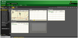 JDLink Dashboard
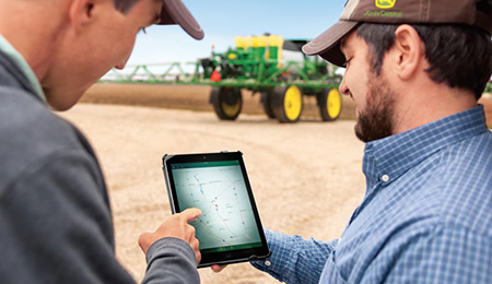
JDLink is the John Deere telematics system designed for operators and managers who desire to take their operations to the next level of productivity and efficiency without leaving the office. Whether it is receiving an e-mail or text message, users can manage the operation in real-time without being in the cab. Using the power of JDLink can optimize productivity, increase uptime, and boost profits with JDLink information all accessible from a laptop, desktop, or mobile device.
JDLink Ultimate provides enhanced machine performance and utilization information that can only be achieved through direct communication with on-board machine controllers. Utilizing John Deere-exclusive telematics technology, users can remotely link to Ultimate-compatible machines to achieve a new level of optimization.
NOTE: Mobile device compatibility and functionality varies.
Monitor assets, performance, and more with JDLink:
- Increase uptime and reduce time spent managing equipment with JDLink Ultimate
- Coordinate machine and labor logistics
- Unleash new possibilities with wireless machine connectivity
- Locate machines on-the-go with the JDLink app for iPhone®, iPad® or Android™ devices
- Leverage common components from the JDLink system to enable remote support and machine monitoring
- Industry-exclusive Service ADVISOR Remote with JDLink (Canada link)
For more information on JDLink activations and subscriptions, visit www.StellarSupport.com.
NOTE: JDLink is not available in all geographic regions.
Service ADVISOR
 Service ADVISOR
Service ADVISOR diagnostics greatly assist in reducing service costs and downtime. It allows the John Deere service technician to readily extract vital information about tractor malfunctions through the Service ADVISOR data port. Diagnostic codes and controller area network (CAN) bus statistics stored by the tractor and visible in the CommandCenter™ display are used by service technicians to isolate, identify, and resolve problems.
Diagnostics and CAN bus statistics are not normally used by the operator. Access and use of trouble codes should only be done by a qualified, factory-trained John Deere service technician.
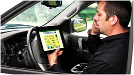
Service ADVISOR Remote
Service ADVISOR Remote takes the machine connectivity of JDLink and takes it one step further. With Service ADVISOR Remote, machines can be diagnosed remotely, saving the cost of a field service call. For example, diagnostic trouble codes can be reset and software updates can be uploaded remotely.
Apple, iPhone, and iPad are trademarks of Apple Inc. Android is a trademark of Google LLC.
e18™ PowerShift™ transmission with Efficiency Manager™ feature
The e18 transmission delivers smooth shifting and intuitive controls in a reliable 18-speed PowerShift transmission. The e18 transmission with enhanced Efficiency Manager is standard equipment on all 9 Family Tractors.
The e18 has evolved from more than 50 years of John Deere PowerShift technology. With more automatic features, the e18 is easy to operate for all levels of operators and operations. It features three modes of operation, full AUTO, custom, and manual modes. Full AUTO and custom modes manage the engine and transmission to match the desired ground speed to the field conditions. These two modes are ideal for most conditions and take the guess work out of operation. Manual mode is perfect for operators looking to operate the e18 like a traditional PowerShift by bump shifting and managing the engine throttle to their liking.
As the next generation of PowerShift technology, the e18 delivers the strength to handle sudden, high-torque power loads while maintaining responsive, quick, and smooth shifts.
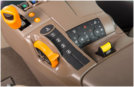
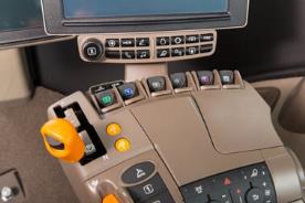
e18 controls
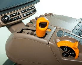 Shift lever and hand throttle
CommandCenter™ controls
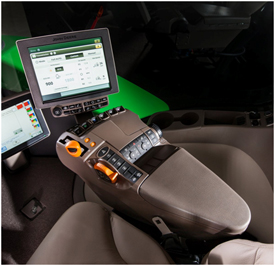 254-mm (10-in.) Generation 4 CommandCenter
The CommandCenter is the central information system for tractors and allows the operator to program various settings tailored to a specific operation.
To access the tractor’s transmission settings, press the transmission shortcut button on the CommandCenter shortcut bar.
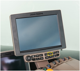 CommandCenter transmission shortcut button
Operating modes
The e18 application settings employ three modes to take full advantage of the engine-transmission communication: Full AUTO mode, custom mode, and manual mode.
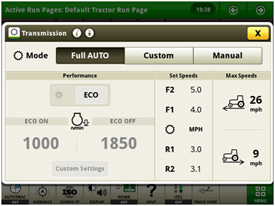
Full AUTO mode
 Full AUTO main page
Full AUTO mode manages the tractor’s engine and transmission inputs to reach and maintain the desired ground speed set by the operator. This means the tractor will manage shifts and engine rpm to operate at the most efficient level possible. Operators have the ability to set the maximum forward and reverse speeds for their particular applications. In full AUTO mode the operator can adjust the desired ground speed in two ways, by conducting a traditional bump shift or by rotating the dial on the thumb wheel.
When shifting in full AUTO mode, the transmission shifts set speeds and does not always shift gears, meaning the transmission may not necessarily shift gears if it can reach the desired ground speed with a slightly higher or lower engine rpm. Efficiency Manager is automatically engaged while operating in full AUTO mode. As a result, shifting will not take the tractor out of Efficiency Manager in full AUTO mode.
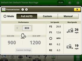
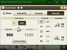
Custom mode
 e18 custom transmission page
Custom mode operates similar to full AUTO mode but allows operators to adjust operating parameters to meet a specific operation. It also has the ability to activate eco mode for a higher level of operation.
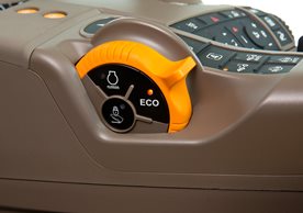
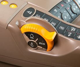 Eco button
 Display screen
Eco allows two minimum engine speeds to be set. Operators can turn eco on and off by either pushing the eco button on the side of the throttle or by selecting eco in the transmission settings page of the CommandCenter controls. For example, operators may choose to turn eco on during transport to utilize a lower minimum engine speed and then turn eco off while operating in the field where a higher minimum engine speed is desired.
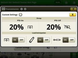 Custom settings page
In the advanced settings page, operators can customize the auto shift engine speed droop as a percentage of the full engine speed. In addition, the load anticipation feature can be enabled for the hitch engagement, hydraulic engagement, or both.
Manual mode
Manual mode operates very similarly to a traditional PowerShift transmission with Efficiency Manager.
In manual mode the operator manages the engine and transmission inputs by controlling the shift lever and hand throttle.
 Manual mode page
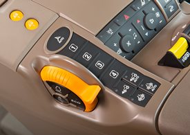
Efficiency Manager
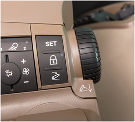
 Set speed buttons and set speed adjuster
Efficiency Manager is automatically enabled in auto and custom modes. Efficiency Manager can be turned on in manual mode by selecting the set speed one or set speed two button on the CommandARM™ console. The set speed adjuster on the top of the single-lever gear selector allows the operator to dial in the desired ground speed to establish set speed one or two. Once engaged, Efficiency Manager will manage the engine rpm and gear selection to maintain the desired working speed. To reach the desired set speed, the throttle must be set to full engine rpm.
e18 operation
 e18 operation
Setting start-up gears
The 9 Family Tractors default to 7F and 2R at start up. However, these default start-up gears can be adjusted from 1-13F and 1-3R through the CommandCenter. Refer to the operator’s manual for additional information.
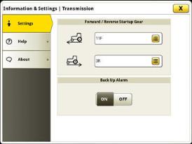 Start-up gears in advanced settings
9R Series Tractor - e18-speed chart for PowerShift transmission with Efficiency Manager
9R table
Group 47 tires |
Group 48 tires |
|||
Tire size |
(480R46, 20.8R42, 520R42, 620R42, 710R38) |
(480R50, 520R46, 620R46, 710R42, 800R38) |
||
Engine (rpm) |
2100 |
2100 |
||
18-speed gear |
km/h |
mph |
km/h |
mph |
Forward gears |
||||
F1 |
4.0 |
2.5 |
4.2 |
2.6 |
F2 |
4.8 |
3.0 |
5.0 |
3.1 |
F3 |
5.3 |
3.3 |
5.6 |
3.5 |
F4 |
5.9 |
3.7 |
6.2 |
3.9 |
F5 |
6.5 |
4.0 |
6.8 |
4.3 |
F6 |
7.3 |
4.5 |
7.6 |
4.8 |
F7 |
8.0 |
5.0 |
8.5 |
5.3 |
F8 |
9.0 |
5.6 |
9.5 |
5.9 |
F9 |
9.9 |
6.1 |
10.4 |
6.5 |
F10 |
11.0 |
6.9 |
11.6 |
7.2 |
F11 |
12.2 |
7.6 |
12.9 |
8.0 |
F12 |
13.5 |
8.4 |
14.2 |
8.8 |
F13 |
15.0 |
9.3 |
15.8 |
9.8 |
F14 |
16.6 |
10.3 |
17.5 |
10.9 |
F15 |
20.5 |
12.8 |
21.6 |
13.4 |
F16 |
25.3 |
15.7 |
26.6 |
16.5 |
F17 |
31.2 |
19.4 |
32.9 |
20.4 |
F18 |
38.5 |
23.9 |
40.5 |
25.2 |
Reverse gears |
||||
R1 |
3.9 |
2.4 |
4.1 |
2.5 |
R2 |
5.3 |
3.3 |
5.6 |
3.5 |
R3 |
5.9 |
3.7 |
6.2 |
3.9 |
R4 |
8.0 |
5.0 |
8.5 |
5.3 |
R5 |
9.0 |
5.6 |
9.5 |
5.9 |
R6 |
12.2 |
7.6 |
12.9 |
8.0 |
Group 47 tire based on 710/70R38
Group 48 tire based on 800/80R38
9RT and 9RX Series Tractor - e18-speed chart for PowerShift transmission with Efficiency Manager
9RT and 9RX table
|
9RT |
9RX |
||
Engine (rpm) |
2100 |
2100 |
||
18-speed gear |
km/h |
mph |
km/h |
mph |
Forward gears |
|
|
|
|
F1 |
4.0 |
2.5 |
4.0 |
2.5 |
F2 |
5.0 |
3.1 |
4.9 |
3.0 |
F3 |
5.5 |
3.4 |
5.5 |
3.4 |
F4 |
6.1 |
3.8 |
6.1 |
3.8 |
F5 |
6.8 |
4.2 |
6.7 |
4.2 |
F6 |
7.6 |
4.7 |
7.5 |
4.7 |
F7 |
8.4 |
5.2 |
8.3 |
5.2 |
F8 |
9.3 |
5.8 |
9.2 |
5.7 |
F9 |
10.3 |
6.4 |
10.2 |
6.3 |
F10 |
11.4 |
7.1 |
11.4 |
7.1 |
F11 |
12.6 |
7.8 |
12.6 |
7.8 |
F12 |
14.1 |
8.7 |
14.0 |
8.7 |
F13 |
15.6 |
9.7 |
15.5 |
9.6 |
F14 |
17.3 |
10.7 |
17.2 |
10.3 |
F15 |
21.4 |
13.3 |
21.3 |
13.2 |
F16 |
26.3 |
16.3 |
26.2 |
16.3 |
F17 |
32.3 |
20.1 |
32.2 |
20.0 |
F18 |
39.8 |
24.7 |
39.6 |
24.6 |
Reverse gears |
|
|
|
|
R1 |
4.0 |
2.5 |
4.0 |
2.5 |
R2 |
5.5 |
3.4 |
5.5 |
3.4 |
R3 |
6.1 |
3.3 |
6.1 |
3.8 |
R4 |
7.3 |
3.8 |
8.3 |
5.2 |
R5 |
9.3 |
5.8 |
9.2 |
5.7 |
R6 |
12.6 |
7.8 |
12.6 |
10.3 |
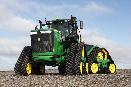
9RX Tractor narrow undercarriage recommended transport speed
9RX Tractors equipped with 45.7-cm (18-in.) and 61-cm (24-in.) tracks feature a maximum speed of 42 km/h (26 mph).
9RX Tractors equipped with 45.7-cm (18-in.) or 61-cm (24-in.) tracks are advised to reduce ground speed based on axle load. 9RX Tractors equipped with 45.7-cm (18-in.) tracks will have a top speed set at the factory of 31 km/h (19 mph). Maximum speed may be adjusted up to 42 km/h (26 mph) upon review of the transport speed recommendations in the Operator’s Manual.
The speed reduction allows the undercarriage components and tracks to dissipate heat buildup caused by the higher axle loads, reducing undercarriage component and track damage. Increasing mid-roller surface area will increase the undercarriage ability to dissipate heat.
Narrow undercarriage with 45.7-cm (18-in.) tracks feature a narrower mid-roller matched to track width. This results in a smaller mid-roller surface area than 61-cm (24-in.) tracks, which are also matched to track width.
Producers who desire a 9RX machine for row-crop work and who also transport long distances with high axle loads should understand the limitations of the 45.7-cm (18-in.) and 61-cm (24-in.) tracks. 61-cm (24-in.) tracks with a greater mid-roller surface area will provide greater undercarriage and machine performance in transport while maintaining the ability to perform row-crop work. Comparing the transport speed recommendations for 45.7-cm (18-in.) and 61-cm (24-in.) tracks, the speed reduction is higher for 45.7-cm (18-in.) tracks for the same axle load.
9RX Tractors with a wide undercarriage and 76.2-cm (30-in.) or 91.4-cm (36-in.) tracks do not feature a speed reduction with increased axle load.
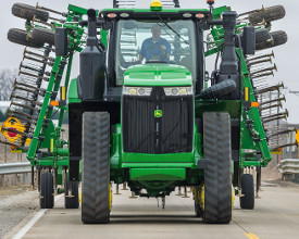 9RX in transport
9RX Tractor owners and operators need to be aware of axle loads and the recommended speed. The operator’s manual for both the machine and implement will have information on advised transport speeds. 9RX Tractors equipped with narrow undercarriage will also feature an in-cab window decal and reference card stored in the armrest for quick guidance on recommended transport speed based on axle load. Many implements may have a lower recommended transport speed than the tractor; it is always advised to follow the lowest recommended transport speed.
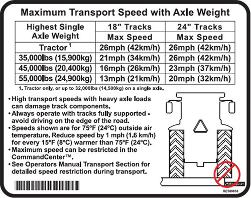 Maximum transport speed with axle weight
Window decal
| Window decal | |||||
| Single axle weight | 45.7-cm (18-in.) track maximum | 61-cm (24-in.) track maximum | |||
| kg | lb | km/h | mph | km/h | mph |
| Tractor | 42 | 26 | 42 | 26 | |
| 15,900 | 35,000 | 34 | 21 | 42 | 26 |
| 20,400 | 45,000 | 26 | 16 | 37 | 23 |
| 24,900 | 55,000 | 21 | 13 | 32 | 20 |
Speed increments
| 1.6-km/h (1-mph) increment | |||||||
| Single axle weight | 45.7-cm (18-in.) track maximum | Single axle weight | 61-cm (24-in.) track maximum | ||||
| kg | lb | km/h | mph | kg | lb | km/h | mph |
| 14,500 | 32,000 | 42 | 26 | 16,800 | 37,000 | 42 | 26 |
| 15,000 | 33,000 | 37 | 23 | 18,100 | 40,000 | 40 | 25 |
| 15,400 | 34,000 | 35 | 22 | 19,500 | 43,000 | 39 | 24 |
| 15,900 | 35,000 | 34 | 21 | 20,900 | 46,000 | 37 | 23 |
| 16,300 | 36,000 | 32 | 20 | 22,200 | 49,000 | 35 | 22 |
| 17,200 | 38,000 | 31 | 19 | 23,600 | 52,000 | 34 | 21 |
| 18,100 | 40,000 | 29 | 18 | 24,900 | 55,000 | 32 | 20 |
| 19,500 | 43,000 | 27 | 17 | 27,200 | 60,000 | 31 | 19 |
| 20,900 | 46,000 | 26 | 16 | ||||
| 22,200 | 49,000 | 24 | 15 | ||||
| 23,600 | 52,000 | 23 | 14 | ||||
| 25,400 | 56,000 | 21 | 13 | ||||
| 27,200 | 60,000 | 19 | 12 | ||||
Implement speed recommendations
| Application | Implement | Payload | Total tractor | Rear axle load | Front axle load | 45.7 cm (18 in.) | 61 cm (24 in.) |
| Other | 18.3-m (60-ft) 2410C applicator | 181 kg (400 lb) | 27,851 kg (61,400 lb) | 13,608 kg (30,000 lb) | 14,515 kg (32,000 lb) | 41.8-km/h (26 mph) | 41.8-km/h (26 mph) |
| Primary Tillage | 9-shank 2720 (without rolling baskets) | 227 kg (500 lb) | 27,896 kg (61,500 lb) | 13,608 kg (30,000 lb) | 14,515 kg (32,000 lb) | 41.8-km/h (26 mph) | 41.8-km/h (26 mph) |
| Primary Tillage | 11-shank 2730 (gangs, without rolling baskets) | 219.5 k g (484 lb) | 27,889 kg (61,484 lb) | 13,608 kg (30,000 lb) | 14,515 kg (32,000 lb) | 41.8-km/h (26 mph) | 41.8-km/h (26 mph) |
| Secondary Tillage | 13.7-m (45-ft) 2210LL Cultivator | 499 kg (1100 lb) | 28,168 kg (62,100 lb) | 14,061 kg (31,000 lb) | 14,061 kg (31,000 lb) | 41.8-km/h (26 mph) | 41.8-km/h (26 mph) |
| Secondary Tillage | 12.2-m (40-ft) 2623 VT | 816.5 kg (1800 lb) | 28,486 kg (62,800 lb) | 14,515 kg (32,000 lb) | 14,061 kg (31,000 lb) | 41.8-km/h (26 mph) | 41.8-km/h (26 mph) |
| Other | 18.3-m (60-ft) 2510L, 9085 L (2400 gal.) (empty) | 1637 kg (3608 lb) | 29,306 kg (64,608 lb) | 15,422 kg (34,000 lb) | 13,608 kg (30,000 lb) | 35.4 km/h (22 mph) | 41.8-km/h (26 mph) |
| Other | 38,763-L (1100-bu) grain cart empty (Kinze 1100) | 1792 kg (3950 lb) | 29,461 kg (64,950 lb) | 15,876 kg (35,000 lb) | 13,608 kg (30,000 lb) | 33.8 km/h (21 mph) | 41.8-km/h (26 mph) |
| Secondary Tillage | 13.7-m (45-ft) 2310 Mulch Finisher | 1905 kg (4200 lb) | 29,574 kg (65,200 lb) | 15,876 kg (35,000 lb) | 13,608 kg (30,000 lb) | 33.8 km/h (21 mph) | 41.8-km/h (26 mph) |
| Other | 52,859-L (1500-bu) grain cart empty (Brent Avalanche 1596) | 1724 kg (3800 lb) | 29,393 kg (64,800 lb) | 15,876 kg (35,000 lb) | 13,608 kg (30,000 lb) | 33.8 km/h (21 mph) | 41.8-km/h (26 mph) |
| Other | 35,239-L (1000-bu) grain cart loaded (Brent 1082) | 2136 kg (4710 lb) | 29,805.5 kg (65,710 kg) | 16,329 kg (36,000 lb) | 13,608 kg (30,000 lb) | 32.2 km/h (20 mph) | 41.8-km/h (26 mph) |
| Other | 52,859-L (1500-bu) grain cart empty (Kinze 1500) | 2381 kg (5250 lb) | 30,050.5 kg (66,250 lb) | 16,783 kg (37,000 lb) | 13,608 kg (30,000 lb) | 30.6 km/h (19 mph) | 41.8-km/h (26 mph) |
| Other | 52,859-L (1500-bu) grain cart empty (Brent Avalanche 1596) | 2495 kg (5500 lb) | 30,164 kg (66,500 lb) | 16,783 kg (37,000 lb) | 13,608 kg (30,000 lb) | 30.6 km/h (19 mph) | 41.8-km/h (26 mph) |
| Other | 38,763-L (1100-bu) grain cart loaded (Kinze 1100) | 2849 kg (6280 lb) | 30,518 kg (67,280 lb) | 17,236.5 kg (38,000 lb) | 13,154 kg (29,000 lb) | 30.6 km/h (19 mph) | 40.2 km/h (25 mph) |
| Other | 38,763-L (1100-bu) grain cart loaded (Kinze 1500) | 3347.5 kg (7380 lb) | 31,017 kg (68,380 lb) | 17,690 kg (39,000 lb) | 13,154 kg (29,000 lb) | 29 km/h (18 mph) | 40.2 km/h (25 mph) |
| Planters | DB60 47R15 CCS | 3783 kg (8340 lb) | 31,452 kg (69,340 lb) | 18,597 kg (41,000 lb) | 13,154 kg (29,000 lb) | 27.4 km/h (17 mph) | 38.6 km/h (24 mph) |
| Planters | DB90 Planter | 5597 kg (12,300 lb) | 33,248 kg (73,300 lb) | 20,865 kg (46,000 lb) | 12,247 kg (27,000 lb) | 25.7 km/h (16 mph) | 37 km/h (23 mph) |
| Planters | 1775NT 24R drawbar | 5897 kg (13,000 lb) | 33,566 kg (74,000 lb) | 21,319 kg (47,000 lb) | 12,247 kg (27,000 lb) | 24.1 km/h (15 mph) | 35.4 km/h (22 mph) |
| Planters | DB120 Planter | 7832 kg (17,600 lb) | 35,652 kg (78,600 lb) | 24,494 kg (54,000 lb) | 11,340 kg (25,000 lb) | 20.9 km/h (13 mph) | 32.2 km/h (20 mph) |
| Other | Hitch load | 6804 kg (15,000 lb) | 34,476 kg (76,000 lb) | 24,494 kg (54,000 lb) | 9979 kg (22,000 lb) | 20.9 km/h (13 mph) | 32.2 km/h (20 mph) |
NOTE: Example implements are for reference and direction only. Weigh the tractor and the amount of weight on the axle to determine the final recommended speed. Weights of implements will vary due to different configurations available between tractor and implement. Never exceed the maximum speed recommendation of any implement.
For producers who wish to limit vehicle top speed, transmission settings can be adjusted on the CommandARM™ display or user profiles can be established which locks out the ability to change vehicle top speed by the operator unless they enter the PIN.
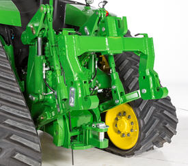
9RX 304.8-cm (120-in.) track spacing options
Beginning with model year 2019 production, 9RX Series Tractors equipped with 76.2-cm (30-in.) and 91.4-cm (36-in.) tracks can be equipped with industry-exclusive, factory-installed track spacing set at 304.8-cm (120-in.).
9RX Series Tractors equipped with 304.8-cm (120-in.) track spacing provide increased stability, allow producers to operate on 304.8-cm (120-in.) centers for controlled traffic farming, and provide improved track-to-frame clearance for better access to the undercarriage for serviceability and material cleanout. John Deere is the first and only tractor manufacturer to offer a 304.8-cm (120-in.) track spacing option on four-track tractors with 76.2-cm (30-in.) and 91.4-cm (36-in.) tracks up to 462.3 kW (620 hp).
 9RX with 91.4 cm (36 in.) tracks and 304.8-cm (120-in.) track spacing
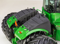
9RX Series Tractors with 304.8-cm (120-in.) track spacing increase space between the undercarriage and chassis to provide more space for performing daily and routine maintenance tasks.
 Performing daily maintenance tasks
 Performing routine maintenance tasks
| 9RX Series Tractors undercarriage configurations | ||||
 |
 |
|||
| Model | Narrow undercarriage | Wide undercarriage | ||
| Track spacing: 203.2 cm (80 in.), 223.5 cm (88 in.), or 304.8 cm (120 in.) |
Track spacing: 223.5 cm (88 in.) or 304.8 cm (120 in.) |
|||
| 45.7 cm (18 in.) tracks | 61 cm (24 in.) tracks | 76.2 cm (30 in.) tracks | 91.4 cm (36 in.) tracks | |
| 9420RX | • | • | --- | --- |
| 9470RX | • | • | • | • |
| 9520RX | • | • | • | • |
| 9570RX | --- | --- | • | • |
| 9620RX | --- | --- | • | • |
• Available
--- Not available
3-point hitch and CommandCenter™ controls boost productivity
3-point hitch
 3-point hitch on 9RX
The 9 Series Tractors are designed to maximize performance for different applications. The 9R, 9RT, and 9RX Tractors offer two different hitch options:
9420R/9420RX |
9470R/9470RT/9470RX |
9520R/9520RT/9520RX |
9570R/9570RT/9570RX |
9620R/9620RX |
|
Category 4N/3 with quik-coupler, all axle diameters |
Optional – 6804 kg (15,000 lb) |
Not available |
|||
Category 4N/3 with quik-coupler, 120-mm (4.7-in.) axles required |
Optional – 9072 kg (20,000 lb) |
Not available |
|||
Category 4/4N with quik-coupler, all diameters axles |
Optional: 6804 kg (15,000 lb) |
||||
Category 4/4N with quik-coupler, 120-mm (4.7-in.) axle required |
Optional: 9072 kg (20,000 lb) |
||||
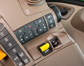
CommandARM™ controls
 Hitch controls
 Field-installed 3–point hitch controls under armrest on CommandARM
To help boost productivity, a field-installed kit with 3-point hitch controls can be purchased. If this option is selected, control buttons will be located on the 9 Series Tractor’s CommmandARM to access individual hitch settings. There are three buttons — set, lock, and load depth. There is also a rotary encoder that allows for finite movements of the hitch. The rotary encoder is detented, so it clicks for each movement. Additionally, hitch adjustment controls are located under the CommandARM for raise/lower rate.
Hitch load depth
The load depth feature is a useful tool designed to increase performance in tillage applications. Load depth adjustments allow the operator to make adjustments to hitch draft responsiveness.
Draft control helps maintain the operating depth in varying conditions, such as rolling terrain, and varying soil densities.
An additional feature with load depth control is the hitch slip option. Hitch slip uses wheel slip data to supplement the draft control system. If the wheels slip, the 3-point hitch lifts to allow the tractor wheels to maintain traction with the ground. Once the slip condition is no longer present, the hitch lowers to the required depth as determined by the hitch command and load depth settings.
Both of these hitch command options are easily programmable in the CommandCenter display by pressing the load depth shortcut key, followed by using the thumbwheel and confirm key to dial in the desired settings.
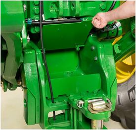
Hitch, external remote control switch
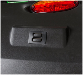 3-point hitch switch on fender of 9R
For added operator convenience, a 3-point hitch remote control switch is located on top of the left rear fender for 9R, 9RT, and 9RX Tractors. The external remote switches enable the operator to raise and lower the 3-point hitch from behind the tractor while hooking to implements.
High-flow hydraulics, 435-L/min (115-gpm) system
Dual hydraulic pump system
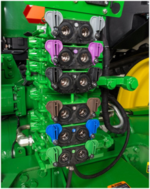 Selective control valve (SCV) stack
Optional high-flow hydraulics are available on 9 Family Tractors by ordering code 3270. The high-flow hydraulic system provides an additional 215 L/min (57 gpm) of flow for a total of 435 L/min (115 gpm). This system is ideal for hydraulic fan motor demands. This system is recommended for agricultural implements with continuous flow requirements. When maximum hydraulic pump capacity is reached, multiple functions will continue to operate at the same proportional flow rate.
The 9 Family Ag High-Flow Tractors have two parallel hydraulic systems. The benefit of this system is that functions can be split between the two systems. Functions that require high flow and low pressure can be combined on one system (for example, air seeder fans, and planter motors). Functions that require high pressure and low-flow can be connected to the remaining system (for example, implement lift, fold, and constant down-pressure systems).
Following these guidelines allows the hydraulic system to run cooler as it prevents both hydraulic pumps from running at high pressure. In general, pumps forced to run at both high pressure and high flows generate much more heat than a pump running at a lower flow or lower pressure.
The system operates with two hydraulic pumps:
- Pump 1 - provides hydraulic flow of up to 215 L/min (58 gpm) to SCVs 1, 2, and 3. These SCVs are useful for operating lift/lower and other cylinder type hydraulic needs.
- Pump 2 - attaches in front of pump 1 and provides hydraulic flow of up to 215 L/min (57 gpm) to SCVs 4, 5, and 6. These SCVs are useful for operating hydraulic motors to drive air/fan or vacuum systems on seeding/planting equipment.
- All SCV oil returns to one common hydraulic reservoir.
Eight-section SCV stack for high-flow requirements
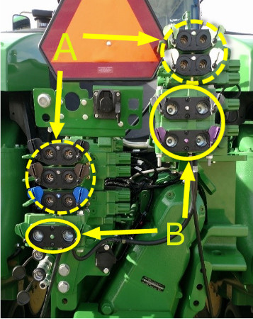 Five 1.3-cm (1/2-in.) couplers (A) and three 1.9-cm (3/4-in.) couplers (B)
For applications requiring continuous high hydraulic flow or multiple 1.9-cm (3/4-in.) hydraulic connections, this SCV stack is designed to maximize efficiency of the hydraulic system while providing additional flow using 1.9-cm (3/4-in.) couplers. Arrangement of the 1.9-cm (3/4-in.) couplers are split between the tractor’s dual hydraulic pumps to even the hydraulic load on each pump. Increasing coupler size from 1.3 cm (1/2 in.) to 1.9 cm (3/4 in.) allows an additional 26.5 L/min (7 gpm) or 17 percent more hydraulic flow through each coupler and reduces backpressure for hydraulic functions such as dual fan motors associated with the Air Power™ 2 system equipped on John Deere C850 Air Carts. With three 1.9-cm (3/4-in.) couplers available, operators can connect to other high-demand functions such as raise/lower. The 1.9-cm (3/4-in.) couplers also allow higher fan motor speeds for high-rate applications and allow more power to the ground due to less restriction on the hydraulic system.
NOTE: This SCV configuration is available on all double-reduction) axle 9420R to 9570R Tractors with high-flow hydraulics and all 9RX Tractors with high-flow hydraulics. This eight-section SCV stack does not include hydraulic Intelligent Power Management (IPM) software.
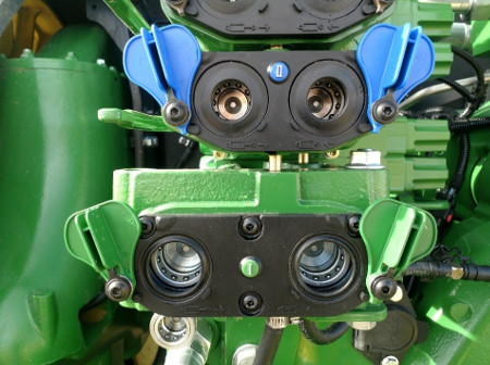 SCV couplers
Connections to 1.3-cm (1/2-in.) and 1.9-cm (3/4-in.) couplers are quick and simple for operators with a split SCV stack configuration at a comfortable connection height.
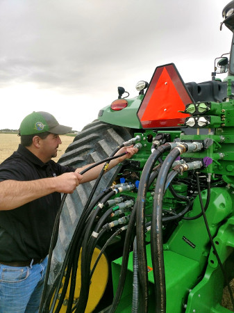 SCV connections in a stack configuration
Power take-off (PTO), 1-3/4 1000 rpm
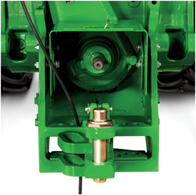 PTO and shield
Fully independent 1000-rpm PTO is available as a factory- or field-installed option.
- Available on all 9 Family Ag Tractors.
- 4.45-cm (1-3/4-in.) diameter shaft.
9R – When the PTO is on and ground speed is 0.5km/h (0.31 mph) or less; PTO is limited to 335 hp.
9RT – When the PTO is on and ground speed is 0.5km/h (0.31 mph) or less; PTO is limited to 329 hp.
9RX – When the PTO is on and ground speed is 0.5km/h (0.31 mph) or less; PTO is limited to 335 hp.
See the specs page for model rated PTO horsepower.
The PTO shield has three positions — neutral, up, and down. Use the neutral position when the PTO is connected and ready for use. Use the up position for added clearance when connecting the PTO shaft to the tractor. The down position is used when the PTO is not connected and extra visibility to the drawbar is desired.
Electrohydraulic PTO control
The 9 Family Tractors utilizes an electrohydraulic PTO-engagement switch to activate the optional 1000-rpm PTO.
If PTO option is not installed, a storage compartment is located on the rear of the tractor.
 Rear storage compartment on 9R
Engine, PowerTech™ PSS 13.5L (824 cu. in.) external efficiency, performance features
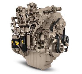 PowerTech PSS 13.5L (824 cu. in.) engine
John Deere has engineered the PowerTech PSS 13.5L (824 cu. in.) engine to meet the high expectations for fuel economy and performance that operators expect.
Selective catalytic reduction (SCR) is an exhaust filter option that reduces NOx emissions. SCR technology increases in cylinder combustion temperatures to reduce particulate matter (PM) output but as a result of these higher combustion temperatures, it increases the NOx (smog) emission levels. To keep the NOx levels within acceptable standards, a urea-based additive, sometimes referred to as AdBlue® system or diesel exhaust fluid (DEF) is added into the exhaust stream to low NOx emission downstream of the engine. The urea mixes with engine exhaust gases in the catalytic converter. The resulting reaction of adding urea (NH3) (or purified fertilizer) into the exhaust stream and passing through a catalyst transforms the NOx which results in harmless nitrogen gas and water vapor.
Series turbochargers
Series turbocharging delivers higher power density, improved low-speed torque, and improved high-altitude operation. By splitting the compression of the charge air between two turbochargers, both can operate at peak efficiency and at slower rotating speeds. This lowers stress on turbocharger components and improves durability.
Series turbocharging works when fresh air is drawn into the low-pressure turbocharger (fixed geometry), where air pressure is boosted. This pressurized or boosted air is then drawn into the high-pressure turbocharger (VGT or WGT), where air intake pressure is further raised. The high-pressure air is then routed to an air-to-air aftercooler, where the air is cooled and routed to the engine’s intake manifold.
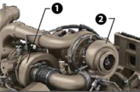 Series turbochargers
- High-pressure turbocharger
- Low-pressure turbocharger
The PowerTech PSS 13.5L (824 cu. in.) utilizes two turbochargers – a variable geometry turbocharger (VGT) and a fixed geometry turbocharger, providing the torque rise and engine responsiveness to meet varying load conditions.
Fresh air is first drawn into the low-pressure fixed geometry turbocharger and compressed to a higher pressure. The compressed air is then drawn into the high-pressure VGT where the air is further compressed. The compressed air is then routed to the charge air cooler, and then to the intake manifold. By splitting the work between two turbochargers, both can operate at peak efficiency and at a slower rotating speed.
VGT
The VGT is electronically controlled and hydraulically actuates the turbo vanes as required to maintain peak engine performance.
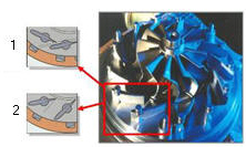 VGT vanes in exhaust flow
The turbocharger’s vanes are in the exhaust flow. The opening or closing of the vanes changes the outlet volume and airflow speed against the turbocharger impeller. When exhaust flow is low, the vanes are partially closed. This partial closure increases the pressure against the turbine blades to make the turbine spin faster and generate more boost pressure. The ability to keep the airflow flowing at optimum levels provides more consistent engine boost pressure and the ability to respond to load quickly across the entire engine rpm range. This system is without turbo lag as can be found on some engines. Boost pressure in the intake manifold is controlled at its optimum point for added fuel economy and performance regardless of rpm or load.
The overall benefits:
- Increased low rpm torque
- Quicker response to load
- Increased peak torque
- Improved fuel economy
- Improved performance at high altitudes
Air-to-air aftercooling
Air-to-air aftercooling lowers the intake manifold air temperature and provides more efficient cooling while reducing cylinder firing pressure and temperatures for greater engine reliability. Since low temperature air is denser, a higher volume of air flows into cylinders so the engine is capable of meeting the increasing horsepower demands.
Electronic unit fuel injection system
 Electronic unit injector
Electronic unit fuel injection system on the 13.5 L (824 cu. in.) engine provides the following benefits:
- Variable timing control for improved emissions
- Better control at start of fuel injection for improved starting
- Elimination of nozzle service
- Camshaft-driven transfer pump draws fuel through the fuel filter
- The single fuel rail is a drilled passage in the head, eliminating the need for external lines for reduced service through the fuel filter
The electronic control unit monitors various sensor inputs from the tractor and automatically changes the sheave ratio to change the fan speed. Hydraulic oil pressure is directed to the pistons that push the top inner sheave out (A), to close the gap and create a larger working diameter.
The bottom sheave (B) responds by compressing the coil spring, widening the gap between the two sheave halves, and creating a smaller working diameter to increase the fan speed.
To slow the fan, the valve opens, allowing oil to leave the piston, widening the upper sheave halves.
Automatic shutdown function
This feature monitors engine coolant temperature, engine oil pressure, and transmission oil pressures while the transmission is in the park position, and the operator is out of the seat. If any of the systems reach undesirable levels, the tractor will shut down, to help prevent further tractor damage.
AdBlue is a trademark of German Association of the Automobile Industry (VDA).
Engine control unit (ECU) - full authority electronic controls
This engine control unit uses signal inputs from sensors and pre-programmed performance modeling to control critical engine functions such as fuel quantity, injection timing, air-to-fuel ratio, multiple fuel injections, amount of cooled exhaust gas recirculation (EGR), and a host of other control parameters to deliver peak fuel economy and engine performance.
Each injector is controlled individually by the ECU. The ECU turns the injector on and off during each firing cycle to control the fuel delivery into each cylinder. The ECU can sense engine speed and load changes at a rate of 100 times per second and respond instantly to them. Load and speed sensing allows each cylinder’s fuel delivery rate to be adjusted independently at the individual injector. With each injection cycle, the ECU can make the following adjustments on the go:
- Number of injections
- Fuel pressure in the common rail
- Start of injection
- Duration of injection
This management system is connected to the transmission allowing the engine and transmission to respond simultaneously.
Cold weather and high altitude compensation are also precisely controlled for quality starts regardless of weather and proper power levels at high elevations.
Noise reduction
The injection system also contributes to the engine running at a decreased noise level by a process called pilot injection. The precise fuel injection capabilities allow a small amount of fuel to be injected early in the combustion process. This helps lessen the combustion knock that is commonly heard on many diesel engines. While the combustion noise reduction is most obvious at lower engine speed, pilot injection continues to function at any engine speed.
Vari-Cool™ system
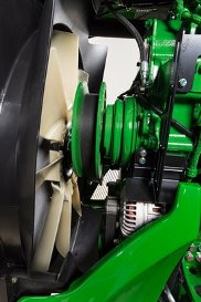 9R cooling package
The Vari-Cool fan drive system precisely controls the speed of the fan in relation to the cooling requirements to maximize efficiency of the engine. The Vari-Cool system is efficient for two primary reasons:
- The belt drive used in the Vari-Cool system transfers almost 100 percent of the power from the engine to the fan.
- The variable fan speed sheave is electronically controlled only operating at the necessary speed to cool the engine and other auxiliary components.
Vari-Cool is integrated into the hood design
The Vari-Cool system is an integrated part of the hood design. Intake and outflow of air from the coolers is diverted to key openings in the hood structure. The design allows for airflow dispersion that lessens dust and crop kick-up by discharging the airflow away from the cab.
How Vari-Cool works
This electrohydraulic system uses variable speed drives. Actual fan speed is determined by the ratio differences of the top fan drive sheave to the bottom sheave.
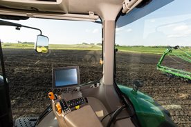
Standard CommandView™ III cab offers unsurpassed amenities
 CommandView III cab
The standard CommandView III cab offers unsurpassed visibility, operator comfort, control placement, and ride and sound quality.
Features:
- ComfortCommand™ seat with air suspension, lumbar support, swivel, fore-aft and lateral attenuation, backrest angle adjustment, adjustable left-hand armrest, and 40-degree right-hand seat swivel
- Operator presence system that warns if the operator is out of the seat while operating key functions
- Folding instructional seat
- CommandARM™ control center with integrated controls
- 4100 or 4600 Generation 4 CommandCenter™ processor
- Behind-the-seat storage
- Left-hand storage compartment
- Passive noise reduction system
- Service ADVISOR™ diagnostic system data port
- Tilt/telescoping steering wheel with position memory
- Swing-out rear window, opens 30 degrees
- Right- and left-outside mirrors (manually adjustable mirror head)
- Monitor mounts on right-hand front post and rear cab post
- Standard radio package, including AM/FM stereo and weatherband with remote controls, auxiliary input jack, four speakers, and an external antenna
- Laminated glass
- Air conditioner and heater with automatic temperature controls (ATC)
- Two 12-V convenience outlet (cigarette lighter style)
- One 12-V 3-pin outlet with adapter (provides switched and unswitched power)
- One International Organization for Standardization (ISO) nine-pin connector
- Power strip with convenience plug adapter
- Hitch control lever lock and selective control lever lock
- Two-speed and intermittent front and rear wiper with washer
- Front pull-down sunshade
- Digital cornerpost display with:
- Fuel level gauge, including low fuel warning
- Temperature gauge
- Diesel exhaust fluid (DEF) gauge, including low DEF warning
- Engine rpm
- Transmission commanded gear or speed
- Vehicle system functions, such as iTEC™ end-row guidance, that are operating
- Inside-mounted rearview mirror
- Beverage holders sized to accommodate various containers
- Interior left-hand dome light
ComfortCommand seat
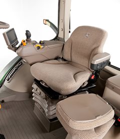 ComfortCommand seat
ComfortCommand seat improves ride quality and helps to reduce operator fatigue
Features include:
- Armrests, lumbar support, and backrest angle are easily adjusted to match operator preference.
- Shock absorbers dampen the motion effect of the tractor for an improved ride.
- Seat height adjustments are conveniently located on the left armrest.
- Fore-aft adjustment is easy to reach located on the left front of the seat.
- Swivel adjustment, located on the front of the seat, allows the seat to be swiveled 40 degrees to the right or eight degrees to the left of the center position.
- Operator presence switch warns if the operator is out of the seat while operating key functions.
- Seat belt retractor.
- Centered cab seat, providing excellent over-shoulder visibility.
- Adjustable shock absorber permitting ride adjustment from soft to firm to match the operator's desired comfort level.
- Removable cushions for easy cleaning.
CommandARM
 CommandARM controls
John Deere 9 Family Tractors feature the CommandARM with integrated Generation 4 CommandCenter display. The control layout of the CommandARM utilizes a clean and efficient design which groups controls by function and builds upon John Deere’s history of intuitive and ergonomic control placement and operation. The design of the CommandARM allows for a 40-degree right seat swivel and adjustable positioning matching the operator’s preference.
Controls located on the CommandARM include:
- Engine throttle
- Transmission control for e18™ transmission speed PowerShift™ transmission
- Eco mode (minimum engine speed) for e18 speed PowerShift transmission
- FieldCruise™ engine controls
- Selective control valve (SCV) controls
- AutoLoad™ controls (if equipped)
- Differential lock on/off and automatic
- iTEC™ sequence switches
- AutoTrac™ assisted steering system resume switch (if equipped)
- Radio
- Beacon light on/off
- Hazard lights on/off
- Field lights 1/2
- Heating, ventilation, air-conditioning (HVAC) system
Hydraulic controls
Hydraulic controls utilize fingertip paddle pots for raise/lower and extend/retract functions.
 Fingertip paddle pots
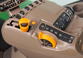
Throttle
The throttle design incorporates buttons which control FieldCruise speed, and transmission eco settings.
 Throttle
Tractor function controls
Located just to the right of the throttle is the Auto-Trac activation button and four sequence controls for iTEC functions. Behind the iTEC sequence controls there are buttons which control the activation and deactivation of differential lock. Differential lock can also be activated by the foot switch on the cab floor.
 AutoTrac resume and iTEC strip
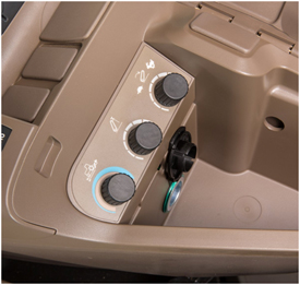
Controls for radio, lights, rotary beacon (if equipped), hazard flashers, and HVAC system are located to the center-right on the CommandARM, along with power take-off (PTO) for rear PTO.
 Radio, HVAC, hazard flashers, and PTO controls
Seat swivel
The design of the CommandARM allows for up to 40 degrees of right-hand seat swivel.
 Seat swivel
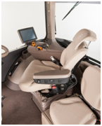 40-degree seat swivel shown
CommandCenter
 Generation 4 CommandCenter
The Generation 4 CommandCenters features fast adjustment of tractor functions and controls and are integrated into the CommandARM to create a seamless control center.
The following functions can be adjusted and accessed using the CommandCenter display:
- Hydraulic settings
- Hitch settings
- Transmission settings
- FieldCruise
- iTEC programming functions
- Radio
- Lights
- Add all functionality – diagnostics, display settings, etc.
The Generation 4 CommandCenter systems have the capability of Remote Display Access (RDA). RDA allows improved communication between an offsite farm manager or dealer and the equipment operator. The user can view exactly what the operator sees on the GreenStar™ 3 2630 Display and Generation 4 CommandCenter from almost any internet-connected device. RDA is available on the 4600 and 4100 CommandCenter and allows for an increase in productivity with quicker problem resolution. By using RDA, the cost of operation will decrease due to reduced labor and travel costs, and maximum efficiency will increase profit.
General maintenance
 9R, 9RT, and 9RX service access
Regular service and maintenance are essential to the performance, productivity, and longevity of all farm machinery.
Maximum uptime is an important element of productivity.
- 9 Series service points are quick and simple to check.
- Greater accessibility improves serviceability.
All items in the daily service schedule can be performed without the use of tools:
- Engine oil, hydraulic oil, coolant level, and water separator can be conveniently accessed from ground level without having to open the hood. Engine oil can be checked by simply removing one small engine side panel.
 Engine oil service point
- Engine can be easily accessed by simply raising the one-piece hood and removing two engine side panels for more periodic maintenance checks.
- Single-point latch mechanism ensures easy hood opening and closure.
NOTE: Always refer to the operator’s manual for complete maintenance and service recommendations.
Refueling
 Fuel tank on the 9R
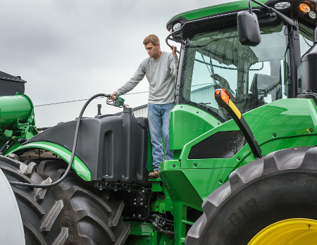 Refueling
The 9R Tractors fuel tank is located over the rear axle. The fuel tank features a dual fill design. This design allows the machine to be filled from either side of the fuel tank. A fuel nozzle holder is located when the operator positions themselves on the gudgeon platform to fill the fuel tank.
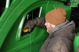
The diesel exhaust fluid (DEF) tank is located on the left-hand side of the tractor indicated by a blue cap. It is fillable from ground level and has a protective shield to keep debris out of the fill neck.
Model |
Diesel |
DEF |
9420R |
1514 L (400 gal.)* | 120 L (31.7 gal.) |
9470R |
1514 L (400 gal.)* | 120 L (31.7 gal.) |
9520R |
1514 L (400 gal.) | 120 L (31.7 gal.) |
9570R |
1514 L (400 gal.) | 120 L (31.7 gal.) |
9620R |
1514 L (400 gal.) | 120 L (31.7 gal.) |
*When equipped with double-reduction axle. 1211-L (320-gal.) when equipped with single-reduction axle.
 Fuel tank on the left side of 9RT
The 9RT fuel tank is located behind the cab; the fuel fill is located conveniently on the left-hand main platform.
The 9RT Tractors all feature a DEF tank capacity of 93.9 L (24.8 gal.). The fill location is near the diesel fill location.
Model |
Diesel |
DEF |
9470RT |
1325 L (350 gal.) | 93.9 L (24.8 gal.) |
9520RT |
1325 L (350 gal.) | 93.9 L (24.8 gal.) |
9570RT |
1325 L (350 gal.) | 93.9 L (24.8 gal.) |
Model |
Diesel |
DEF |
9470RX |
1514 L (400 gal.) | 120 L (31.7 gal.) |
9520RX |
1514 L (400 gal.) | 120 L (31.7 gal.) |
9570RX |
1514 L (400 gal.) | 120 L (31.7 gal.) |
9620RX |
1514 L (400 gal.) | 120 L (31.7 gal.) |
NOTE:
- John Deere supports the usage of bio diesel. Bio diesel should meet ASTM D6751 (US) or EN 14214 (European) fuel quality standards.
- Tractors receive fuel containing a 2 percent bio-diesel blend at the factory.
- Acceptable blend levels may vary by geographic region.
- Diesel exhaust fluid will freeze when exposed for longer than three hours to conditions below -11°C (12.2° F).
For more information about the use of bio-diesel in John Deere engines, refer to www.JohnDeere.com/biodiesel.
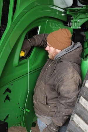
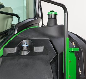
DEF fill
9R, 9RT, and 9RX Tractors feature an easy-to-use DEF fill system. The 9R and 9RX feature a ground-level fill location, and DEF fill on 9RT is conveniently located on the step platform.
| Machine | DEF tank capacity |
| 9R | 120 L (31.7 gal.) |
| 9RT | 93.9 L (24.8 gal.) |
| 9RX | 120 L (31.7 gal.) |
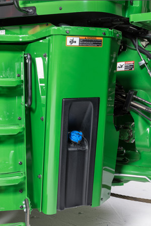 DEF tank on 9R/9RX
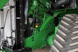
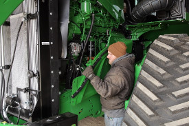
Engine access
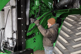 Engine access on 9RX
The tilt hood and side panel design provides additional engine compartment protection. The 9R, 9RT, and 9RX hoods feature the same design for access to engine components.
Pull out the hood release (located on the front, left side) and tilt hood back to open. Engine side panels are quickly and easily removed for access to periodic maintenance items.
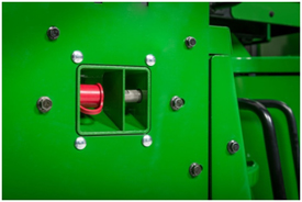
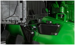
In-line DEF filter
9R, 9RT, and 9RX Tractors feature an in-line DEF filter to help protect the DEF pump from any contamination in the DEF tank. This in-line DEF filter is easily serviced with a drain plug to drain any remaining DEF from the filter housing and a replaceable cartridge-style filter.
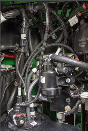 In-line DEF filter
Severe-duty water separator, if equipped
The severe-duty water separator can extend service intervals and helps to protect the tractor’s fuel system from damage associated with lower-quality fuel.
Simply open the drain valve on the bottom of the separator and drain accumulated water.
NOTE: Cummins® QSX 15 L (915.4-cu in.) engines cannot be equipped with a severe-duty water separator; however, the fuel filter has separating capabilities like the primary filter on John Deere Power System engines.
 Removing side engine panel
Transmission, hydraulic, and axle oil level
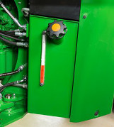 Sight gauge on 9R and 9RX
 Sight gauge on 9RT
A sight glass for the transmission, hydraulic, and axle oil level is located at the back right side of the gudgeon, indicating proper oil levels, and an oil fill neck is located on the back right side of the gudgeon for the 9R and 9RX Tractors. The oil fill is located on the top of the common reservoir on the left side of the 9RT Tractor and a fill tube is located between the steps and engine of the tractor.
- Provides increased filter capacity compared to previous 9R and 9RT Tractors
- Transmission, hydraulic, and axle oil should be changed every 1500 hours
- Filter should be changed every 1500 hours unless filter restriction code occurs
- Daily and 10-hour inspections of the transmission hydraulic oil level are recommended
NOTE: The tractor should be off and parked on level ground with the hitch in the lowered position when checking the oil level.
- Sight glass observations will be significantly higher with hot oil temperatures and lower with cold oil or if engine has not run long enough.
NOTE: Oil level above the top mark on the sight glass can result in power loss and heat generation during transport applications.
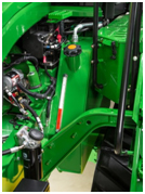
Battery boost terminal
 Battery boost terminal
On the 9R and 9RX, a battery boost terminal is located on the left-hand side of the engine for convenient and proper boost assisted starting.
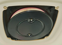
Primary air filter access
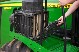 Primary engine air filter inspection
On the 9R and 9RX, the primary engine air filter is accessible from the left-hand platform for replacement annually or as operating conditions require. The filter is aspirated and extends filter life in dusty conditions by aspirating more than 95 percent of incoming dust. Aspirator suction is created by utilizing the air flow from the cooling fan.
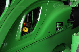
On the 9RT, the primary engine air filter is located at ground level on right side of tractor.
Oil change intervals
 Engine oil check/fill location
Tractors with the 9.0L (549.2-cu in.) and 13.5L (823.2-cu in.) John Deere Power Systems engines feature a 500-hour change interval when using approved John Deere Plus-50™ II oil and a John Deere oil filter.
Tractors equipped with the Cummins QSX 15-L (915.4-cu in.) engine have a 400-hour engine oil and oil filter change interval.
- Previous initial oil and filter change at 100 hours is no longer required due to the factory fill of Break-In™ Plus oil.
- If using anything other than John Deere Plus-50 II oil, a 250-hour change interval is required. CJ-4 must still be used.
- Only use ultra-low sulfur diesel fuel and CJ-4, ACEA E9, or ACEA E6 oil.
- An oil change of 500 hours is possible when using fuel with less than 15 parts per million (ppm) of sulfur, along with John Deere Plus-50 II oil.
See the tractor's operator's manual for oil change intervals and further details.
Battery access
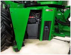 Battery location on 9R and 9RX
 Battery location on 9RT
The 9R and 9RX battery location is behind the left-hand step assembly. There are three bolts that secure the swinging step assembly that need to be removed to completely access the batteries. The 9RT top step of the platform conceals the tractor’s three 12-V batteries with 2775 CCA (925-CCA each). Tractors with the Cummins X15 engine will have four 12-V batteries in the same location as tractors equipped with John Deere Power System engines.
Although the batteries are maintenance free, conditions such as long periods of operation at high ambient temperatures and excessive engine cranking may require adding water.
Windshield washer
 Windshield washer bottle on 9R and 9RX
The windshield washer bottle is optional on 9R and 9RX Tractors and is located on the left side of the tractor near the DEF fill point. On 9RT Tractors, it is located on the right-side frame.
Maintenance-free U-joint
Maintenance-free U-joint bearings require no servicing to reduce maintenance time.
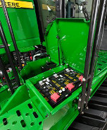
Fuse and relay panel
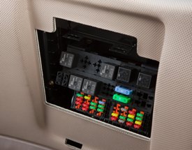 Fuse and relay panel
The electrical fuse and relay panel is located behind the operator’s seat and just below the cab's rear window. Simply lift up on the operator manual cover for access.
- Contains easy-to-replace automotive blade-type fuses and relays for quick servicing.
- Spare fuses are provided for each amperage size used.
The diode module contains many of the diodes contained in the system:
- If a diode problem occurs, simply replace the diode module for easy service and increased uptime.
- Relays are also fully interchangeable for quick service.
Electrical system (smart load center)
The electrical system provides a full controller area network (CAN) bus based system on the tractor for improved tractor implement integration and flexibility. Incorporated with the system is a smart load center, which provides fewer fuses, fewer connectors, and simplified wiring for increased reliability.
The solid-state load center’s primary function is to control the majority of high-current loads, such as fender floodlights and the horn. This electronic circuitry will monitor loads and voltages to provide fast reaction time and the ability to alert the operator if a circuit overloads or if voltage is out of specification – for example, open circuit (undercurrent) or short circuit (overcurrent).
Cab air filters
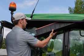 Cab fresh air filter inspection
 Cab recirculation filter
The cab fresh air filter is conveniently located beneath the left side of the cab for all 9 Series products:
- External service means no mess in the cab from dusty filters
- Filter housing acts as a dust accumulator compartment
- Hand screw eliminates need for tools
- Replace cab fresh air filter every 1000 hours or sooner if plugged or damaged
Cab air recirculation filter
Cab air recirculation filter is located in the roof liner above the operator. 70 percent of the total air volume is recirculated with a blanket effect for enhanced operator comfort.
- Replace cab air recirculation filter every 1000 hours or sooner if plugged or damaged.
Cab air filters are not designed to filter out harmful chemicals. Follow the instructions in the implement operator’s manual and those given by the chemical manufacturer when using agricultural chemicals.
Toolbox
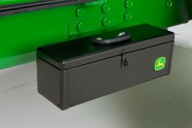 Toolbox for 9R, 9RT and 9RX
A convenient toolbox is located on the left-hand side of the front frame for tool storage and comes standard on all 9R, 9RT, and 9RX Tractors.
9R and 9RX Tractors have an additional storage box conveniently located on top the left-hand platform.
The 9RT has an additional toolbox conveniently located next to the left side of the batteries for additional storage.
Cummins is a trademark of Cummins, Inc.